Medical Exhibits - Demonstrative Evidence Expert Blog - MediVisuals

Medical Legal Illustration and Animation - Cross Sections

Posted by Tara Rose on Mon, Jun 18, 2012

By: Robert Shepherd MS, Certified Medical Illustrator, Vice President and Director of Eastern Region Operations,MediVisuals Incorporated

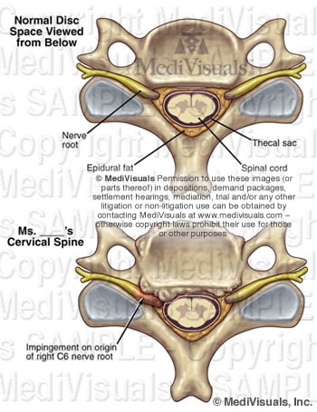
Long before science had advanced to allow imaging of the body in sectional views by computed tomography (CT) and magnetic resonance imaging (MRI), medical illustrators were illustrating the body in sectional views because these views are the best way to appreciate some anatomical relationships. 

Medical illustrators, physicians, and others who have studied anatomy are familiar with sectional views of the body and appreciate the value of these views in explaining the relationship of anatomical structures. However, accomplished and well respected jury consultants and non-medical illustrator legal graphics experts have expressed concerns that sectional views may be difficult for some jury members to understand. These individuals' opinions are valuable to those of us in the legal graphics business, and I agree with their opinions that, when other views can communicate a particular relationship message equally as well or better, sectional views should be avoided. I also believe most of these experts will agree that there are times and places in which sectional views of anatomy are the best way to appreciate some anatomical relationships. Granted, there have been times when we have been working on specific cases and experts have insisted that sectional views be absolutely and unconditionally avoided. Unfortunately, in these situations the experts were unable to suggest a more effective view to communicate the relevant anatomical relationships (at least in a way that was practical in terms of time and expense). That being the case, sometimes the sectional views were used despite the input of the experts, and at other times, the relationships of the structures had to be explained without the benefits of graphics.

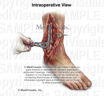
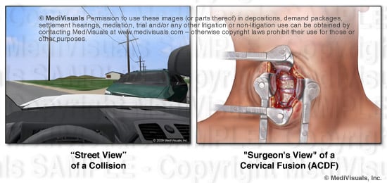
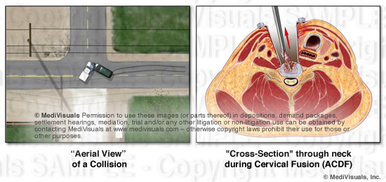
A way to perhaps explain how sectional views help decision makers appreciate relevant anatomical and pathological relationships is to compare them to aerial views or photographs of the scene of a collision.  Space is defined in three planes. Only two of these planes can effectively be demonstrated in a two-dimensional rendering. For example, aerial views have long been used to help explain the positions of vehicles and structures that simply can't be appreciate from "street views". When viewing the scene of a collision from a "street view", one can appreciate vertical and horizontal distances, but not depth; distances close to and far from the viewer's perspective are very difficult to appreciate (see the below figures). By comparison, when viewing an operative site through a "surgeon's view", vertical and horizontal distances can be appreciated, but the depth of the incision and the relationships of the various structures within and around the incision are very difficult or impossible to appreciate.


Cross Section Blog image1 REVISED


The "aerial view" of the collision scene allows the viewer to appreciate distances in two geographical planes as well (distances right and left, and toward and away from the "street view," but the ability to appreciate up and down is lost). Also, the locations of relevant structures or vehicles that may have been obstructed by nearby structures (such as buildings trees, signs, or other vehicles) can now be appreciated. Similarly, a sectional view of anatomy can help decision makers appreciate depth relationships of structures. Or, a sectional view of a step in a surgical illustration can allow the viewer to appreciate the depth of the surgery as well as the additional structures that may have been injured (or at risk of injury) during the invasive procedure.  These specific depth  relationships could not be appreciated from the "surgeon's view" of the same surgery shown in the above illustration.


Cross Section Blog image2 REVISED


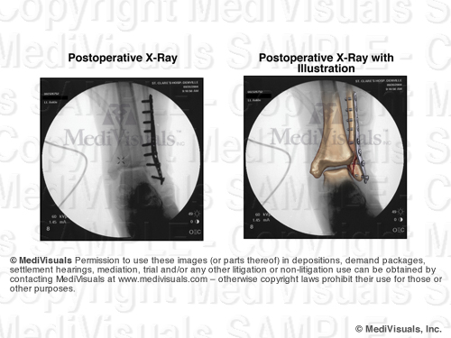
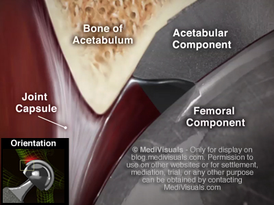
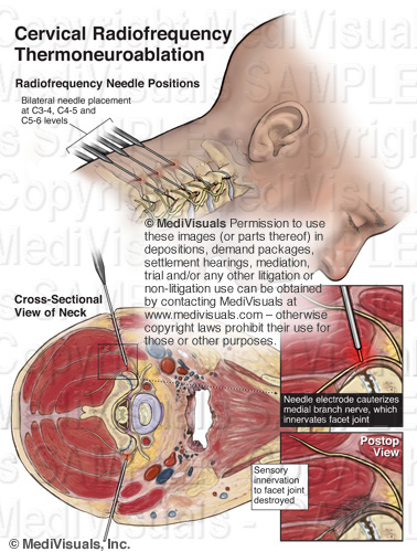
Exhibits developed to help explain the invasive nature of a surgery and the disruption of the soft tissues during operative procedures are critical. For that reason, sectional views are critical in aiding a testifying physician to explain these issues. For example, the exhibit panel that demonstrates an anterior cervical discectomy and fusion (ACDF) that does not include a cross-section through the neck fails to emphasize the depth of the incision and disruption of tissues (essentially all the way to the center of the neck). This depth simply cannot be appreciated in a "surgeon's view".

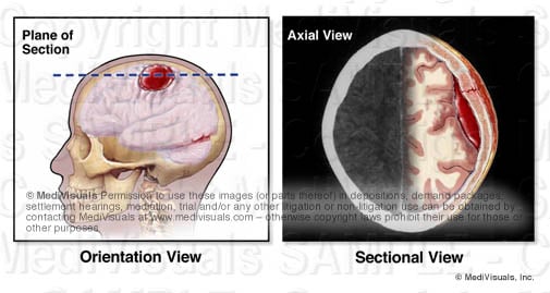
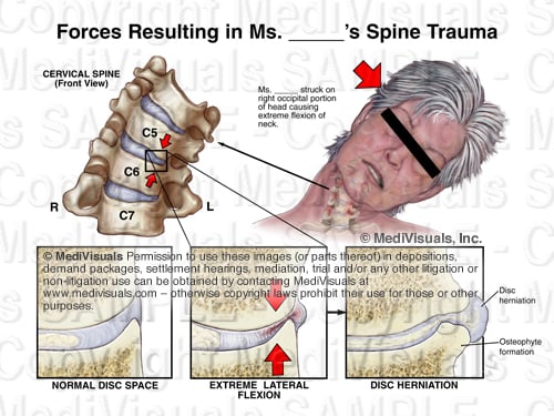
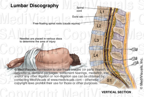
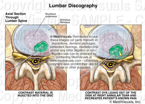
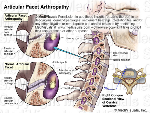
In order to appreciate cross-sections, orientation views that show the level and direction of the section are helpful (see below), or when time, budget, and presentation format (digital as opposed to a physical panel) allow, a short animation showing the sectional view actually coming out of the orientation view such as MediVisuals' "Scan SelectorTM" can be used.


cross-section plane of brain hematoma

Topics: intervertebral disc, coup-contracoup, medical-illustrator, trial exhibit, disc herniation, degenerated disc, disc bulge, trauma, hematoma, traumatic-brain-injury, medical exhibits, medical-legal-illustration, disc injury, brain, TBI, medical expert, intracranial, surgery, MediVisuals, medical exhibit, personal injury, spinal injury

Disc-Osteophyte Complex Explained

Posted by Delia Dykes on Wed, May 2, 2012

By: Robert Shepherd MS, Certified Medical Illustrator, Vice President and Director of Eastern Region Operations, MediVisuals Incorporated

Individuals who develop new or suddenly worsening symptoms consistent with nerve root or spinal cord impingement following a traumatic event are sometimes diagnosed with “disc-osteophyte complexes”. The term “disc-osteophyte complex” generally refers to abnormal extension of intervertebral disc material that accompanies immediately adjacent osteophyte formation at the vertebral body margin (see the below figure). It is important to note (as shown in the illustrations) that the disc almost always extends further than the osteophytes into the neural foramen or spinal canal to irritate or impinge upon nerve roots or the spinal cord.


DiscOstCompBlogASTAMP


Occasionally, individuals who are evaluated shortly after a traumatic event are found to have disc-osteophyte complexes. Because a minimum of several weeks is required for osteophytes to form as a result of a traumatic event, defendant insurance companies may argue that the presence of osteophytes so soon after the traumatic event in question may prove that the plaintiff’s injuries preexisted the traumatic event. Since it is the disc pathology extending beyond the osteophytes that is the actual cause of the nerve root or spinal cord irritation and inflammation, the defense’s arguments are not valid. As shown in the illustrations below, the sequence of events that typically takes place in these cases is that the plaintiff had minimally symptomatic or asymptomatic disc osteophytes prior to the traumatic event in question. During the traumatic event, the disc sustains trauma that results in worsening of the disc pathology while the osteophyte portion of the osteophyte/disc complex remains essentially unchanged. This worsening of the disc pathology in turn results in new or increased irritation or impingement of the neural elements.


DiscOstCompBlogBSTAMP

Topics: intervertebral disc, medical-illustrator, trial exhibit, disc herniation, disc bulge, trauma, medical exhibits, medical-legal-illustration, disc injury, MediVisuals, medical exhibit, personal injury, spinal injury, osteophyte, cervical strain

Intra-operative Trauma: The Overlooked Injuries

Posted by Delia Dykes on Wed, Oct 19, 2011

By: Robert Shepherd MS, Certified Medical Illustrator, Vice President and Director of Eastern Region Operations, MediVisuals Incorporated

The surgical trauma that a plaintiff has to undergo after the initial bodily injuries following a traumatic event are always major points of emphasis when arguing damages in a personal injury case.  This is certainly the situation with cases that involve broken bones that require invasive surgical procedures to realign broken bone fragments ("reduce") and secure ("fixate") the bones with hardware to keep them properly aligned during healing.  Too often, however, the emphasis is solely on the effects on the bones from these "Open Reduction and Internal Fixation" (ORIF) procedures, and very little emphasis is placed on the surgical disruption of the soft tissues that takes place during these procedures.

In a case involving ORIF of a distal fibula (a.k.a. lateral malleolus) fracture, in order to emphasize the surgical trauma endured by a plaintiff, an attorney may have a visual prepared of a postoperative X-ray.  The visual may consist of only a postoperative X-ray or a print of the X-ray with a corresponding illustration (see the below figure). 


SurgTraumBlog01STAMPED

The above images are certainly helpful, but fail to address the intra-operative trauma to the soft tissues that is required to gain access to the bone fragments.  For that purpose, intra-operative illustrations that truthfully depict the soft tissue disruption should be considered (see the below figure) or even an animation showing the procedures such as the one at this link: http://www.medivisuals.com/fibularplatingORIF.aspx

Illustrations or animations that at least touch on the soft tissue disruption allow testifying physicians the opportunity to explain the many tissues traumatized during the procedure and allow insurance adjustors, mediators, and jurors an opportunity to take these additional injuries into consideration when determining the severity of a plaintiff's entire injuries.


SurgTraumBlog02STAMPED


Many attorneys considering realistic illustrations such as the one above, express a concern that judges may not allow the images to be used because they are too "graphic" or "inflammatory".  Certainly, counsel should make themselves aware and consider the preferences of certain jurisdictions and specific judges before determining whether an illustration should be developed that realistically depicts injuries or whether diagrammatic (cartoon-like) illustrations should be developed instead.  There are a number of very good arguments to support the use of "realistic" illustrations over "cartoons".  Those arguments as well as other discussions regarding illustration styles will be addressed in future blogs.


Topics: demonstrative evidence, soft tissue injury, trial exhibit, trauma, ankle, medical-legal-illustration, surgery, fracture, MediVisuals, medical exhibit, personal injury

Knee Prosthesis Failure Animation (Cementless CoCrMo Alloy)

Posted by Trisha Haszel Kreibich on Thu, May 26, 2011

By: Robert Shepherd MS, Certified Medical Illustrator, Vice President and Director of Eastern Region Operations, MediVisuals Incorporated

The following animation contains sequences that are intended to help support expert witness testimony regarding one of the causes of failure of certain types of knee prostheses (such as the Zimmer NexGen knee prosthetic).

The animation focuses on the cementless cobalt-chromium-molybdenum (CoCrMo) alloy prosthesis. It compares how new bone normally fuses with a prosthesis versus how ions emitted from the CoCrMo alloy inhibit osteoblasts (cells that are responsible for bone formation) from forming new bone. Fibroblasts (cells responsible for fibrous tissue formation, such as collagen) are less inhibited by the CoCrMo ions; therefore, the fibroblasts form fibrous tissue between the bone and prosthesis. This weak and inadequate fusion allows movement and loosening between the femur and prosthesis resulting in prosthesis failure.

Knee Prosthesis Failure Animation Button

Topics: knee replacement, trial exhibit, implant failure, prosthesis, cementless, Zimmer NexGen, medical exhibit, cromium cobalt alloy

Understanding the Osteophyte/Disc Complex in Spinal Trauma

Posted by Trisha Haszel Kreibich on Fri, Apr 8, 2011

By: Robert Shepherd MS, Certified Medical Illustrator, Vice President and Director of Eastern Region Operations, MediVisuals Incorporated

A traumatic event causing injury to an intervertebral disc may also cause subtle injuries to the bones around the disc. During an extreme lateral flexion injury (shown in the image below), the edges of the bone are driven together, injuring both the disc and the bone. As the bone/disc junction heals, overgrowths referred to as osteophytes may form.

Osteophyte Formation From Trauma

Osteophytes take weeks or months to develop following a traumatic event; therefore, any osteophytes that are present soon after a traumatic event are likely pre-existing.

Cervical Spine Osteophytes

The osteophytes themselves may compress the neural elements as in the illustration above; however, in most situations, the osteophytes are a part of an OSTEOPHYTE/DISC COMPLEX. This is when the osteophytes and disc extend beyond their normal limits and compress the neural elements (spinal cord, nerve roots). In cases where osteophytes may have pre-existed a traumatic event, worsening of the disc bulge could occur following the trauma, resulting in new or aggravated symptoms.

Sagittal Spine Osteophyte Disc

Sometimes disc and ligament injuries occur on the same side as the force of impact. Other times, they occur on the opposite side. Injuries to the disc on the same side as the force are the result of stretching and tearing forces. On the opposite side, compression forces result in tears and micro fractures of the tissues and bones. (see illustration below). Osteophytes and facet hypertrophy can also form following injuries to intervertebral discs and ligaments. Injuries to the discs and ligaments result in instability and excessive motion of the joints that, in turn, results in constant trauma to the bone/disc and ligament junctions. This ongoing trauma results in overgrowth of the bones as it continually cycles through episodes of healing and reinjury.

Spine Trauma Forces Osteophyte Disc

Topics: mechanism of injury, intervertebral disc, hyperflexion, trial exhibit, trauma, disc injury, personal injury, osteophyte

Visualizing the Metal-on-Metal Hip Replacement Implant Failure

Posted by Trisha Haszel Kreibich on Thu, Feb 3, 2011

By: Trisha Kreibich, MS Medical Illustrator/Consultant and Robert Shepherd MS, Certified Medical Illustrator, Vice President and Director of Eastern Region Operations, MediVisuals Incorporated

There has been a lot of buzz about the DePuy Hip Replacement Implant Recall, but few visual aids are available to help people understand the mechanism behind the implant's failure.

In order to provide attorneys and physicians with the tools needed to help explain this effectively to the people with these implants and their families, MediVisuals has created the Metal-on-Metal Hip Replacement Recall Animation Series. The first of this series focuses on (1) the metal on metal wear and (2) how placement of the acetabular component at too steep an angle significantly increases the pounds/mm2 pressure on the devices resulting in increasing friction and metal discharge into the joint space.

This article will explain the sequences through a series of screen shots taken from the animation. A link to view the full animation is available at the end of the article. (First, we recommend reviewing the surgical steps involved in a typical hip replacement procedure, by clicking the following link: Total Hip Replacement Surgery Animation)

The image below shows the pelvis and hip anatomy. The left hip [appears on right side of image] is normal, while the right hip [appears on the left side of image] has a hip replacement implant.

Hip Replacement Recall Pelvic Anatomy

The next image shows a detailed view of the implant. The STEM is inserted into the reamed femur. Attached to the stem are the FEMORAL COMPONENTS. These articulate with the ACETABULAR COMPONENT, which is inserted into the reamed acetabulum of the pelvis. The femoral components and acetabular component together create the familiar "ball-and-socket" joint that allows for a wide range of movement.

Hip Replacement Recall Implant Components

As shown in the image below, the desired 45 degree angle placement of the acetabular component results in the majority of the weight-bearing forces being placed on the upper-outer portion of the ball and socket (edge loading). In many cases, the acetabular component is placed at a steeper angle. When placed at an angle of 52 degrees or greater, the amount of force on the edge of the ball and socket is significantly higher and, as the animation will proceed to show, so is the failure rate of the implant.

Hip Replacement Recall Edge Loading

In a normal hip and most hip replacements, synovial fluid is able to enter the joint space and provide lubrication. However, some implants are manufactured in a way that the space between the femoral head and acetabular components is so tight that the synovial fluid is unable to enter the joint space.

Hip Replacement Recall Anatomy

Without this necessary lubrication, the result is direct metal-on-metal wear. The combination of the increased weight-bearing surface and direct metal-on-metal wear results in tiny metal fragments, or ions, fracturing off into the joint capsule.

Hip Replacement Recall Metal Fragments

These metal fragments (ions) irritate the joint capsule and surrounding tissues, triggering an immunological response known as metallosis. This condition can lead to inflammation, weakness, pseudotumors, and eventual necrosis of the tissues around the joint.

Hip Replacement Recall Metal Irritation Pseudotumor

Prolonged exposure increases the concentration of metal ions in the body. This build up can adversely affect numerous physiological systems of the body, and may also increase the risk of development of cancer in some patients. For these reasons, the removal of the implant and replacement with a different device (revision surgery) must be strongly considered, even in situations where the patient is not suffering from noticeable complications associated with the recalled implant. 

Hip Replacement Recall Metal Bloodstream

To view the full animation, please click the image below or the following link: Understanding Edge Loading, Metal Fragment Discharge, Inflammation & Metallosis Associated with Metal-on-Metal Hip Replacement Implants To view additional medical exhibits related to this topic, please visit the following MediVisuals webpage: Metal-on-Metal Hip Replacement Recall Animation Series

Hip Replacement Recall Animation

Topics: mass tort, trial exhibit, hip implant, mechanism of failure, medical exhibit, DePuy, product liability

Attorneys: Reduce Travel Time and Expenses when Meeting with Medical Experts

Posted by Trisha Haszel Kreibich on Wed, Jan 12, 2011

By: Robert Shepherd MS, Certified Medical Illustrator, Vice President and Director of Eastern Region Operations, MediVisuals Incorporated

It is now possible for two or more people to simultaneously "share" computers from anywhere in the world through web conferencing. One of the best applications we at MediVisuals have found for this software is to enable the attorney, medical expert and medical illustrator to review and discuss imaging studies simultaneously from their respective offices.

Web conferencing significantly reduces travel time and expense. For example, a recent case required us to team up with a testifying expert located in the Midwest and an attorney in another region. Instead of meeting face-to-face, we tried screen-to-screen contact and found it worked remarkably well. Web conferencing enabled all three of us to maneuver through the imaging studies and move the cursor to specific areas of the films that were being discussed. This, along with simple telephone conferencing, allowed us all to speak with each other as we viewed the same images on our respective computer screens.

Web conferencing makes it easier than ever for us to work with attorneys and medical experts anywhere in the world. The required software programs are simple to use and affordable. The main hurdle involves ensuring the other participants' computers have fast and reliable Internet connections (i.e. DSL or Broadband) and that their web browsers are up-to-date to support the software. Confirming the second/third party Internet and computer capabilities takes no more than a phone call.

Most web conferencing software providers offer a free trial and quick web tutorial, which decreases the learning curve associated with understanding a new program. For the real tech-savvy, some developers even offer applications adaptable to 3G and 4G Smartphones and devices such as the iPad.

If you are interested in introducing web conferencing to your firm, the following is a list of links to recommended software providers’ websites:

Log Me In
http://www.logmein.com

Go To Meeting
http://www.gotomeeting.com

Cisco WebEx
http://www.webex.com/

Yugma
https://www.yugma.com/

MegaMeeting.com
http://www.megameeting.com/

Topics: medical-illustrator, trial exhibit, medical expert, medical exhibit, web conference

"Minimally Invasive" Spine Treatments: Discography, Injections & Ablation

Posted by Trisha Haszel Kreibich on Thu, Dec 2, 2010

By: Robert Shepherd MS, Certified Medical Illustrator, Vice President and Director of Eastern Region Operations, MediVisuals Incorporated

On occasion, it is uncertain exactly which intervertebral disc may be causing a plaintiff’s pain.  Physicians may conduct a discography study prior to surgery in these cases.

Lumbar Discography Exhibit

This procedure involves advancing needles into the discs in question and injecting contrast material that serves two purposes:  (1) The contrast material makes it possible to better analyze the exact defects (if any) in the discs when X-rays or CTs are taken after the administration of the contrast material. (2) The contrast material also increases the pressure within the disc causing it to expand and subsequently compress the nearby nerve roots.  If     the pain corresponds to the patient’s normal pain, then that disc is determined as the     “problem disc”.

Lumbar Discography

When pain is thought to be associated with irritation or inflammation of the nerve root(s) or surrounding tissues, epidural injections can be performed. As shown in the animation below, epidural injections involve administering anesthetics and steroids around the nerve root(s).  These injections can be used as a diagnostic tool as well as a treatment.

Epidural Injection Movie 300

If the epidural injections are ineffective, the cause of the pain may not be related to the nerve root(s).  If the injections are effective, it confirms the nerve root(s) as the source of the pain. Repeated treatments may resolve the pain; if not, more aggressive treatments may be necessary.

Sometimes the facet joints themselves can be the source of pain. One of the terms used to refer to this condition is “facet arthropathy”.  This condition results from the breakdown of the normal, healthy joint spaces. With the breakdown of these articular surfaces, the joints become painful with each movement.

Facet Arthropathy Exhibit

Each facet joint is supplied by a small dorsal branch of the adjacent nerve root [see illustration below].  Injections in or around the facet can again serve to determine the painful facet(s) and help resolve the pain.

Lumbar Facet Injection

If facet joint injections are unsuccessful at resolving the pain, the nerves to the facets can be destroyed by a procedure known as ablation. Ablation involves advancing a needle adjacent to the facet nerve and destroying it, thereby eliminating the pain.

Ablation of Nerve

Topics: facet arthropathy, trial exhibit, disc herniation, degenerated disc, disc bulge, disc injury, ablation, facet joint, spinal injury, epidural injection, discography

Understanding the Brachial Plexus Injury: Part 2 (Shoulder Dystocia)

Posted by Trisha Haszel Kreibich on Fri, Nov 5, 2010
By: Trisha Kreibich, MS, Medical Illustrator/Consultant, and Robert Shepherd, MS, CMI, Medical Illustrator, Executive Vice President and Operations Director, Eastern Region MediVisuals Inc

This article is a continuation of a two part article on brachial plexus injury. Part 1 covered brachial plexus injuries in adults caused by a traumatic event, such as a motor vehicle collision. Part 2 will address brachial plexus injury in infants during delivery, which is also known as Shoulder Dystocia or Erb's palsy.

To review, the brachial plexus innervates the arm and is formed by several of the cervical nerve roots and the T1 nerve root. [see illustration below]

Pediatric Brachial Plexus

During delivery, the infant's passage through the birth canal can be stopped by the impaction of its shoulder(s) against the mother's pubic bone, sacral promontory, or both. [see illustration below]

Shoulder Dystocia

Injury to the brachial plexus may sometimes occur because of unusually powerful uterine contractions or rapid fetal descent; however, brachial plexus injury may also result from improper obstetrician interaction. When excessive downward traction on the head of an infant with shoulder dystocia is applied (a violation of the standard of care), the delicate brachial plexus is stretched and injured. [shown below] The same may also occur when vacuum extraction is used in this situation.

Shoulder Dystocia and Excessive Traction

As in adult brachial plexus injuries, the earlier the injury is identified and treated, the better chances are for recovery and preventing permanent damage. However, this is also dependent on the severity of the initial injury. Sometimes, an overgrowth of nerve cells (neuroma) can form around the injured nerves. When this occurs, surgical intervention and nerve grafting may be needed. [see illustration below]

Sural Nerve Graft

There are some delivery techniques that can be used to prevent brachial plexus injury in infants with shoulder dystocia. As the illustration below demonstrates, the mother is moved to the McRoberts position, where her legs are hyperflexed to the abdomen, typically resulting in an increase of the outlet. This is often used in conjuction with an episiotomy, a cut made in the perineal body (tissue between the vagina and anus) before delivery, to enlarge the outlet and allow the obstetrician more room to perform maneuvers.

McRoberts Position

If no progress is made, moderate suprapubic pressure may be applied to free the impacted shoulder. The Wood's screw maneuver [shown below] may be used as well. This maneuver involves the obstetrician rotating the infant's anterior or posterior shoulder, and in turn the body, like a screw, freeing the impacted shoulder.

Woods Screw Maneuver 604058 03X

The following animation was developed to show how brachial plexus injuries can occur in a shoulder dystocia case, along with a few of the above mentioned accepted procedures that can be performed to help prevent this injury.

Shoulder Dystocia Animation

Reference:

Gabbe, S.G., Niebyl, J. R., & Simpson, J.L. "Obstetrics: Normal & Problem Pregnancies." 3rd ed. Philadelphia: Churchill Livingstone, 1996. 374-375, 490-494. Print.

Topics: mechanism of injury, brachial plexus, Erb's palsy, trial exhibit, medical-legal-illustration, birth trauma, medical exhibit

Understanding the Brachial Plexus Injury: Part 1

Posted by Trisha Haszel Kreibich on Thu, Oct 21, 2010

By: Robert Shepherd MS, Certified Medical Illustrator, Vice President and Director of Eastern Region Operations, MediVisuals Incorporated

Injuries to the brachial plexus can often take place from trauma similar to that which causes cervical spine injuries and can also manifest similar symptoms. As shown in the illustration below, the brachial plexus is formed by several of the cervical nerve roots and the T1 nerve root.

Brachial Plexus 205299 02XA

Sometimes injury to the brachial plexus can be the direct result of excessive stretch during a traumatic event. For example, in a motor vehicle collision with a violent side impact the nerves on the contralateral side of the impact (and resulting flexion) may be stretched and/or torn. [see illustration below]

Brachial Plexus R14893 05X

Injury to the surrounding muscles can indirectly cause injury to the brachial plexus, as well. The brachial plexus runs between the anterior and middle scalene muscles, which connect the cervical spine and first rib. In a motor vehicle collision, hyperextension of the neck may excessively stretch these muscles, as demonstrated in the illustration below.

Brachial Plexus 306036 01XB

When these muscles are stretched, the resulting swelling or spasm can result in symptoms consistent with cervical nerve root injury even though the cervical nerve roots or brachial plexus themselves may not be directly injured. [see illustration below]

Brachial Plexus 205299 02XB

Thoracic outlet syndrome is another mechanism by which the brachial plexus can be injured. The illustration below shows that the axillary sheath, which contains the nerves from the brachial plexus and the axillary vein and artery, passes through the opening created between the clavicle and first rib.

Brachial Plexus 399048 04Apart2

Thoracic outlet syndrome can occur either by (1) the elevation of the first rib due to spasm of the scalenes or (2) the loss of innervation to the trapezius and/or other muscles that insert on the clavicle or scapula, causing the shoulder to droop [see illustration below]. By either mechanism, the opening between the clavicle and first rib is closed and the nerves and blood vessels that travel through the thoracic outlet become compressed.

Brachial Plexus 399048 04Apart1

As one can see in the illustration below, an injury to the brachial plexus affects the motor and sensory function of the arm. The earlier the injury is identified and treated, the better chances are for recovery and preventing permanent damage. However, this is also dependent on the severity of the initial injury. Sometimes surgical intervention is needed to address torn/ruptured nerves and excessive scarring.

Brachial Plexus R16249 01XB

This is the first of a two part article. Please check back to read Part 2, which discusses brachial plexus injury in infants during delivery (Shoulder dystocia). You can also sign up for email alerts, which announce when another article has been posted.


Topics: brachial plexus, Erb's palsy, trial exhibit, medical-legal-illustration, birth trauma, shoulder dystocia, throacic outlet syndrome, medical exhibit